MiNi PA eBay 70 W MOSFET amplifier
We've all seen switching FETs used as PA devices in HF radios, I've experimented with them a few times, lashing up circuits using IRF520s and, my favourite, the FQP13N10, they can produce some useful power for such a cheap device and if you drive them hard, they give some serious power, at 24 volts, with a shade over 3 watts drive I've measured 45 watts output at 30MHz from a single device into a dummy load (you really don't want to put one on the air like that though, the output was horrible)
When you drive them hard, they're fragile, gouts of smoke, chunks of epoxy encapsulation flying across the room and dead fuses are easy to obtain so, I gave up, 'proper' RF devices aren't that much more expensive and are designed for use in radios.
So, why am I talking about them again?
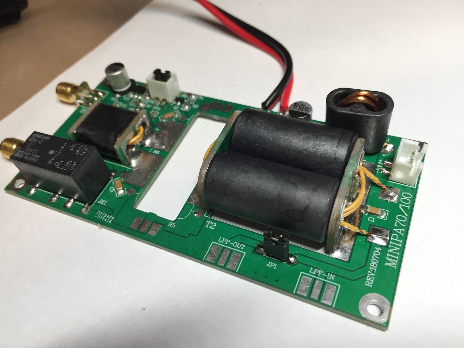
Well, I bought myself one of the Chinese eBay specials, a Mini PA 70W HF amplifier that uses a pair of IRF520* devices to produce a reputed 70 Watts output. (I've no idea what Bobbi is or why they're prohibitied)

 It's cheap, £12.99 shipped, the PCB is suprisingly good quality, the parts look to be good quality with an Omron relay and all the SMD parts presoldered so all you have to do is build the transformers and solder a few easily managed parts then bolt it to a suitable heatsink (not supplied but I'm using a large, fan cooled CPU heatsink)

 The 'Omron' relay.
 One thing that did surprise me, the listing clearly shows IRF520 devices, but for some odd reason they've ground the markings off the supplied parts, I've no idea what these are except 'MOSFET'..
It's hardly important as I bought it to experiment with so it's going to have a few different devices installed in it anyway (Including a significant upgrade).
 Simple to build, it took about an hour including sanding down the rough spots where the ends of the transformers were snipped out.
I'm not building any low pass filters just yet, I want to see the raw nastiness of it.
When you drive them hard, they're fragile, gouts of smoke, chunks of epoxy encapsulation flying across the room and dead fuses are easy to obtain so, I gave up, 'proper' RF devices aren't that much more expensive and are designed for use in radios.
So, why am I talking about them again?
Well, I bought myself one of the Chinese eBay specials, a Mini PA 70W HF amplifier that uses a pair of IRF520* devices to produce a reputed 70 Watts output. (I've no idea what Bobbi is or why they're prohibitied)


There seem to be a few extra bits in the package, four TO-220 insulators
and five insulating bushes for a device that only has two TO-220
devices but that's better than having to scrounge round for bits that weren't supplied.


It's hardly important as I bought it to experiment with so it's going to have a few different devices installed in it anyway (Including a significant upgrade).
I'm not building any low pass filters just yet, I want to see the raw nastiness of it.


Hello. I'm still trying to figure out the coil windings, primarily the center tapped windings. The images I have seen online look only like the input and output windings but I don't see the center tap windings. Am I missing something? Thanks! N3HXT
ReplyDeleteThe centre tapped 'windings' are the PCB end pieces and brass tubes which pass through the binocular ferrites.
DeleteStudying the circuitboard it looks like the "coils" are actually stripline tracks on the board. Oh well....
ReplyDeleteThey aren't. The coils are the windings on the ferrites and the brass tubes that pass through the ferrites to solder to the end PCBs.
Delete